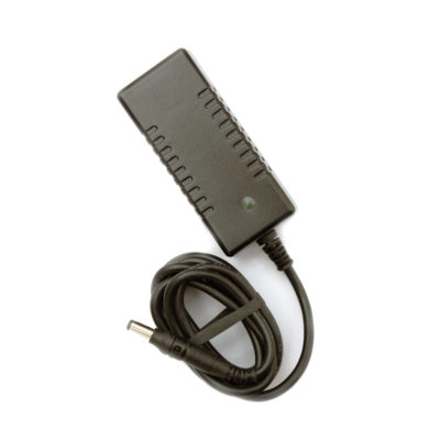
RF500A Gateway for RF500 Wireless Monitoring System
Part No: RF500A/UK (4902133)We will be obsoleting RF500 system at the end of 2022. Find out more information, including the last order date and FAQs.
The RF500A Gateway for Wireless Monitoring is used to control Comark’s RF500 wireless temperature and humidity monitoring system and to provide an economic and flexible solution to most measurement applications.
- Monitors Temperature, Humidity and Door Events
- Full Record-Keeping and Choice of Alarm Notification via Screens, E-Mail, SMS or Voice
- Multi-User Access via Web Browser – No Software Required
- Warranty: 2 Years

Gateway for Wireless Monitoring
The RF500A Gateway for Wireless Monitoring is used to control Comark’s RF500 wireless temperature and humidity monitoring system and to provide an economic and flexible solution to most measurement applications.
Self-healing network properties, data encryption and automatic data retrieval ensures high data integrity with elimination of data loss.
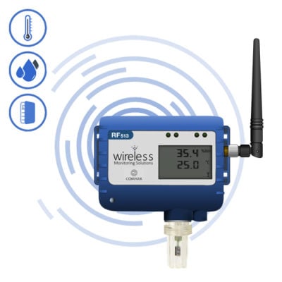
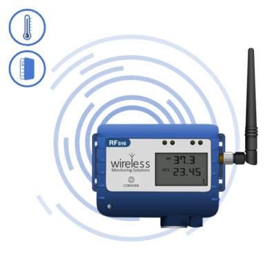
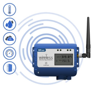
For details of Transmitters see entries for RF512, RF513, RF515 and RF516.
- Solid state memory via two SD cards
- Automatic backup between the two cards provides additional data protection
- Monitors temperature, humidity and door events
- Full record keeping and choice of alarm notification via screens, email, SMS or voice
- Multi-user access via web browser – no software required
- Aids HACCP compliance as required by EU Regulation 852/2004
- An essential component of a 21 CFR Part 11 system
This Product is available in the variants shown below, each comes with a power supply suitable for that region:
- RF500A (4902133) – UK Version
- RF500A/EU (3927721) – EU Version
- RF500A/AUS (4088006) – Australian Version
- RF500A/USA (3927717) – US Version
Technical Specifications
| Name | Value |
|---|---|
| Channels | Up to 256 |
| Transmitters | Up to 64 |
| Storage Capacity | Up to 10 years storage |
| RF Frequency | 2.4GHz (Using IEEE 802.15.4 physical layer and proprietary application layer) |
| Centre Frequency | 2.405 GHz |
| Bandwidth | 5MHz |
| Transmitted Power | 1mW |
| Raw Data Rate | 250 Kbs |
| Actual Throughput (Estimated) | 2Kbps |
| Modulation Technique | QPSK (Quadrature Phase Shift Keying) with half sine pulse shaping modulation |
| Spread Spectrum Technique | DSSS |
| Operating Range | 0°C to +40°C / +32°F to +104°F, 10-90% RH non-condensing |
| Power Adaptor | 100-240VAC 310mA 50/60Hz |
| Battery Backup | 4.3Ah Ni-Mh Rechargeable Battery. Running time approx 1 hour |
| Power Sources | AC power adaptor, rechargeable NiMh battery |
| Clock Accuracy | 4ppm (2 minutes per year) |
| Relay Outputs (SW1 &SWT) | Two individual 2.5mm jack sockets. Contacts: 24Vdc 500mA maximum |
| Power Consumption | 12W typical |
| Dimensions | L 225mm x W 150mm x D 40mm |
| Weight | 1.3Kg |
| Default IP Address | 192.168.25.220 |
| Storage Allocations | Bytes per day = 50KB (No Transmitters), 50KB x 30 Transmitters = 1.5MB per Day, 5.475GB over 10 Years |
| Operating System | Linux running Apache Server version 1.3.33. Kernel version 2.4.31 |
| Warranty | 2 Years |
*You will need to Sign In to view additional content
Documentation
Downloads
Articles / FAQs
| Name | Date | ||||||||||||||||||||||||||||||||||||||||
|---|---|---|---|---|---|---|---|---|---|---|---|---|---|---|---|---|---|---|---|---|---|---|---|---|---|---|---|---|---|---|---|---|---|---|---|---|---|---|---|---|---|
RF500A QSG – New Features Comark RF500A Version M9 (+)RF500A QSG – New Features Comark RF500A Version M9 (+)New Features for M9(+) UpdateOverviewComark’s new RF500A Software interface, version M9, has been designed from the ground up, to enhance the user experience, with a fresh look and feel, along with a number of new features. These include; new RAG Notification Screen; Multi-Graphs which can now be created and saved for later/repeat usage; new Calendar function throughout to select to and from periods for graphing and reporting, such as the Audit Trail and Alarm Events. ICONS are now used throughout for all Gateway and Transmitter notifications, complete with Hover Text for easy diagnosis. All new Tabulated Report for daily tabular temperature and humidity data. Speed of response improved throughout the website. Requires a compatible browser, please see below for more information. New Features
Browser CompatibilityM9 Software for RF500 leverages the power of the Browser, installed on the PC, to provide the rich new user experience and as such, you may need to upgrade, or install another Browser on your PC. If you are using Microsoft Internet Explorer (IE) and only IE, then this will need to be upgraded to IE11 to enable you to use the new interface features. If you are already using Mozilla Firefox, or Google Chrome, then M9 should work for you already. It is advisable to contact your IT if you believe that your current Browser is not compatible with M9 or if you need to install another Browser, as some companies restrict upgrading. Note: M9 can only be used with Google Chrome, Mozilla Firefox or Internet Explorer Version 11 or later. Can I still use the old HTML Interface?Yes you can. There is a link on the new login page for those customers who prefer not to use the new interface, or who are using features not included in the new M9 interface, such as languages, loading pictures and the MAP. However, even though you are planning to use the old HTML interface you still have to upgrade your Browser, as discussed above. What Instructions are there on navigating the new Software?New instructions for using the new Software are going to be made available here on the Comark Portal. Search for ‘RF500A QSG’ in the Search Bar for Knowledgebase Articles on the new Software. | 11th August 2015 | ||||||||||||||||||||||||||||||||||||||||
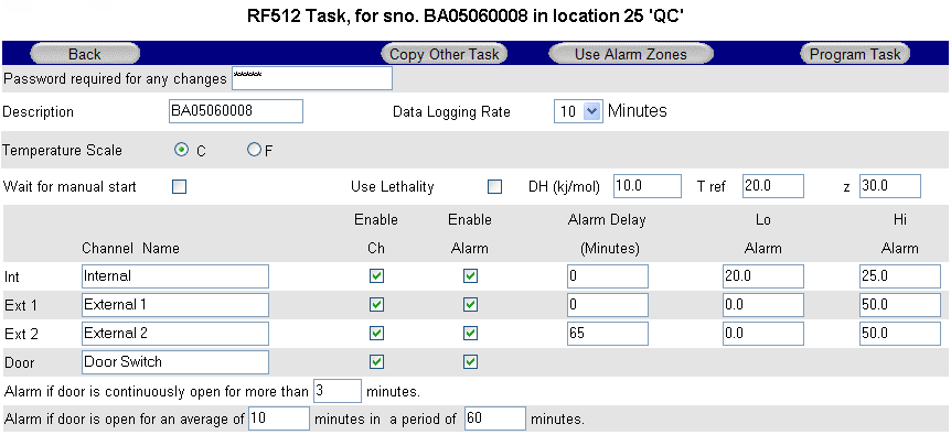
Tasking a TransmitterTasking a TransmitterTransmitter Task Data cannot be collected from a Transmitter until a Task has been programmed. To create a new Task, click the Task button on the Transmitter Graph Button Bar. The Transmitter Task page will appear.
Transmitter Task
Transmitter Task – Button Bar Copy Other Task Link to copy Tasks from other transmitters of same model for quick programming. Program Task Enter your password and click to send new Task to transmitter. Transmitter Task – Tasking Once the Program Task button is clicked, the Daily Readings Summary on the Gateway Home Page will indicate No Data and qT to indicate Tasking. It can take several minutes for the Task to be sent to the transmitter because the Gateway must first wait for the transmitter to contact it. Transmitter Task – RF515 The Task page for RF515 deserves special mention because it is very different from other transmitters, in that this page caters for both regular task setup and also configuration of scale mapping between analog units and engineering units of the sensor.
Task Setup for RF515 Sensor Type Select the option to match the sensor output
Units Engineering units for sensor (Up to 8 characters available) Decimal Places The number of decimal places required for engineering units (0 to 5) Display xxxxx as yyyyy These 2 sets of numbers define the scale mapping between measured units (V or mA) and sensor units. The example for Ext1 shows 4-20mA mapping to 0-100%RH Lo Alarm & Hi Alarm Alarm limits are entered using engineering units for the sensor. The allowable range of values for yyyyy in the Display xxxxx as yyyyy field and also in Lo Alarm & Hi Alarm depends on the number of decimal places selected. See the table below. Decimal Places Range
Transmitter Alarms The graph below shows a temperature profile for a transmitter tasked for 15 minutes log rate, the High Alarm at 5.0 and Low Alarm at 1.0, and 5 minute alarm delay.
Transmitter Alarms
Points B and G correspond to data records which generate alarm Events. They cause the transmitter to have an unacknowledged alarm which in turn generates alerts according to the Location in which the transmitter is placed. These alarm Event records are shown as entries in the Transmitter Events Page and in the Audit Trail. Door Alarms RF500 includes two types of Door Alarm: Continuous Door Alarm – Alarm on Door continuously open for a period of more than X minutes Average Door Alarm – Alarm on Door open for more than X minutes cumulatively in a given period of up to 60 minutes. This alarm captures many individual shorter door open times that may fail to trigger a continuous door alarm but are nonetheless still important.
Date / Time Fence Gate A representation of tabular data shown above shows a typical reading. The readings reported for the door channel are given as two values:
The percentage gives a measure of how much time a door actually spends opened which could represent a problem in a real world application. Consider the following scenario: A door to a laboratory is monitored using RF500 and the continuous alarm is set to 20 minutes to capture a “door left open” event. If that door is opened then closed after 19 minutes have elapsed, then immediately opened again for 19 minutes then closed, the continuous alarm event would not have been generated; however that door has effectively been open for 38 minutes during the previous 40 minutes or so. With an averaging interval of 60 minutes the RF500 system would report a door reading of approximately 63% or with an averaging interval of 40 minutes a door reading of close to 100% would be reported. It may be the case that this high level of “door open” condition may cause environmental controls to be overloaded. Dynamic Alarms Dynamic alarms allow the transmitter to vary the alarm limits or indeed disable alarms for each 30 minute time-slot throughout a 7-day period. Typical uses for this feature include cycling incubators which cycle between temperatures and chillers which are only active for certain times during the week. From the Task Setup page, click the Use Alarm Zones button to activate this function. The fixed alarm limits for each channel are replaced by Dynamic Times buttons. For each enabled channel, click the Dynamic Times button to configure the alarm limits for each time-slot of the 7-day period.
Dynamic Alarm Setup Each cell represents the alarm limits for a 30 minute time slot the first beginning at midnight 00:00 and the last beginning at 23:30. Enter up to four sets or zones of alarm limits as required. To allocate an alarm zone to each cell first click the Slot coloured block to the left of the alarm zone then click the cell to allocate to the selected zone. The area above the M representing Monday, shows which alarm zone has been selected. (In the Figure above the 20.0 to 40.0 zone has been selected and the cell for Tuesday 12:30 is about to be clicked yellow.) To quickly set the entire grid to one alarm zone click the Set All colour to the right of the chosen alarm zone. When done click the OK button on the button bar. Dynamic Alarms for Door Switch Setup of dynamic alarms for Door Switches is as per temperature or RH channels except only the average alarm limit for Door can be changed dynamically, the continuous alarm limit remains in effect at all times. | 20th April 2015 | ||||||||||||||||||||||||||||||||||||||||
What happens to my RF500 System in the event of a power failure?What happens to my RF500 System in the event of a power failure?In the event of a mains power failure, the RF500 System Gateway will continue to work as normal for the following durations:
However, your network might not be operational. If an alarm goes off and you have an Autodialler, then so long as the battery back-up is working this too will continue to work and try to send phone messages, subject to the phone line being operational. Backbone Transmitters will also continue to work. Battery life of a Backbone Unit on just battery power is up to 4 days in total. Our Annual Service plan for RF500 systems will check and replace your batteries and make sure your system is in full working order. For more information, please contact us. | |||||||||||||||||||||||||||||||||||||||||
How do I set up alarms?How do I set up alarms?The Set-up of Transmitter Alarms on your RF500 System Gateway, can only be done at the time of tasking the Transmitter. This Knowledgebase Article will explain how to task your Transmitter including Alarms. Transmitter TaskData cannot be collected from a Transmitter until a Task has been programmed. To create a new Task, click the Task button on the Transmitter Graph Button Bar. The Transmitter Task page will appear.
Transmitter Task
Transmitter Task – Button BarCopy Other Task Link to copy Tasks from other transmitters of same model for quick programming. Program Task Enter your password and click to send new Task to transmitter. Transmitter Task – TaskingOnce the Program Task button is clicked, the Daily Readings Summary on the Gateway Home Page will indicate No Data and qT to indicate Tasking. It can take several minutes for the Task to be sent to the transmitter because the Gateway must first wait for the transmitter to contact it. Transmitter Task – RF515The Task page for RF515 deserves special mention because it is very different from other transmitters, in that this page caters for both regular task setup and also configuration of scale mapping between analog units and engineering units of the sensor.
Task Setup for RF515Sensor Type Select the option to match the sensor output 0V to 1V Units Engineering units for sensor (Up to 8 characters available) Decimal Places The number of decimal places required for engineering units (0 to 5) Display xxxxx as yyyyy These 2 sets of numbers define the scale mapping between measured units (V or mA) and sensor units. The example for Ext1 shows 4-20mA mapping to 0-100%RH Lo Alarm & Hi Alarm Alarm limits are entered using engineering units for the sensor. The allowable range of values for yyyyy in the Display xxxxx as yyyyy field and also in Lo Alarm & Hi Alarm depends on the number of decimal places selected. See the table below. Decimal Places Range 0 ±32000 Transmitter AlarmsThe graph below shows a temperature profile for a transmitter tasked for 15 minutes log rate, the High Alarm at 5.0 and Low Alarm at 1.0, and 5 minute alarm delay.
Transmitter Alarms
Points B and G correspond to data records which generate alarm Events. They cause the transmitter to have an unacknowledged alarm which in turn generates alerts according to the Location in which the transmitter is placed. These alarm Event records are shown as entries in the Transmitter Events Page and in the Audit Trail. Door AlarmsRF500 includes two types of Door Alarm: Continuous Door Alarm – Alarm on Door continuously open for a period of more than X minutes Average Door Alarm – Alarm on Door open for more than X minutes cumulatively in a given period of up to 60 minutes. This alarm captures many individual shorter door open times that may fail to trigger a continuous door alarm but are nonetheless still important.
Date / Time Fence Gate A representation of tabular data shown above shows a typical reading. The readings reported for the door channel are given as two values:
The percentage gives a measure of how much time a door actually spends opened which could represent a problem in a real world application. Consider the following scenario:
Dynamic AlarmsDynamic alarms allow the transmitter to vary the alarm limits or indeed disable alarms for each 30 minute time-slot throughout a 7-day period. Typical uses for this feature include cycling incubators which cycle between temperatures and chillers which are only active for certain times during the week. From the Task Setup page, click the Use Alarm Zones button to activate this function. The fixed alarm limits for each channel are replaced by Dynamic Times buttons. For each enabled channel, click the Dynamic Times button to configure the alarm limits for each time-slot of the 7-day period.
Dynamic Alarm Set-upEach cell represents the alarm limits for a 30 minute time-slot the first beginning at midnight 00:00 and the last beginning at 23:30. Enter up to four sets or zones of alarm limits as required. To allocate an alarm zone to each cell first click the Slot coloured block to the left of the alarm zone then click the cell to allocate to the selected zone. The area above the M representing Monday, shows which alarm zone has been selected. (In the Figure above the 20.0 to 40.0 zone has been selected and the cell for Tuesday 12:30 is about to be clicked yellow.) To quickly set the entire grid to one alarm zone click the Set All colour to the right of the chosen alarm zone. When done click the OK button on the button bar. Dynamic Alarms for Door SwitchSetup of dynamic alarms for Door Switches is as per temperature or RH channels except only the average alarm limit for Door can be changed dynamically, the continuous alarm limit remains in effect at all times. | |||||||||||||||||||||||||||||||||||||||||
The MAX, MIN and AVE readings are missing from the Home PageThe MAX, MIN and AVE readings are missing from the Home PageThe lack of MAX, MIN and AVE readings from the Home Page of your RF500 System Gateway is normal for the new 2015 Interface. If you want to view MAX, MIN and AVE readings for the Transmitter in question please switch to ‘List View’. If you are using the old HTML interface of the RF500 System Gateway, then this suggests that there is a fault with the channel in question. Check the Summary Page to check to see if there is live data for the channel. If in doubt then please contact us for further advice. | |||||||||||||||||||||||||||||||||||||||||
There is — instead of readings on the Home PageThere is — instead of readings on the Home PageOn the Home Page of your RF500 System Gateway, ‘—‘ is shown where there are no data records for the current Daily Interval. This might be indicative of another problem with the Transmitter in question, so it is important to check that it is connected to the Gateway and not showing as ‘No Signal’. If a Task and Data Retrieve command has been requested, then the data could still be coming in. When the data is up to date then the Home Page will update with current readings. This Knowledgebase Article only applies to the HTML interface of the RF500 System Gateway. If in doubt then please contact us for further advice. | |||||||||||||||||||||||||||||||||||||||||
There is -X- instead of readings on the Home PageThere is -X- instead of readings on the Home PageOn the Home Page of your RF500 System Gateway, ‘-X-‘ is shown where a Channel has been in a Fault condition during the current Daily Interval. After the Fault is cleared, the next Daily Interval will show normal readings. This Knowledgebase Article only applies to the HTML interface of the RF500 System Gateway. | |||||||||||||||||||||||||||||||||||||||||
There is a sensor fault message on the Home PageThere is a sensor fault message on the Home PageIf you get a sensor fault message on the Home Page of your RF500 System Gateway, then you should check the condition of the Transmitter referenced and importantly its probe and connection. If possible, we suggest that you swap the probe for another known good working one, in order to eliminate the probe as the source of the problem. If the Transmitter in question just has an integral sensor (RF513) or the connected probes have all been tested on other devices and found to be working OK, then you will need to contact us, as your Transmitter could be faulty. | |||||||||||||||||||||||||||||||||||||||||
There are errors on the page or parts of the page are not being displayed correctlyThere are errors on the page or parts of the page are not being displayed correctlyIf you get errors or elements of the HTML pages are missing/corrupt then we urge you to contact us, advising us of this problem. | |||||||||||||||||||||||||||||||||||||||||
When I look at my Transmitter Summary Graph there are unexplained gapsWhen I look at my Transmitter Summary Graph there are unexplained gapsThere should never be gaps in the Transmitter Summary Graph data under normal operation of the system. Therefore, if there are gaps in the data, then we urge you to contact us, advising us of this problem. | |||||||||||||||||||||||||||||||||||||||||
I get an error when I try to create a manual back-upI get an error when I try to create a manual back-upIf you get an error when asking for a Manual Back-up to be created then we urge you to contact us, advising us of this problem. | |||||||||||||||||||||||||||||||||||||||||
The login page is visible but I get an unexplained error when I log in.The login page is visible but I get an unexplained error when I log in.If you get errors when trying to log in that are not immediately explainable then we urge you to contact us, advising us of this problem. | |||||||||||||||||||||||||||||||||||||||||
How to setup RF500 E-mails and SMS TextsHow to setup RF500 E-mails and SMS TextsEmail SetupThe primary method for remote notification of Transmitter Alarms and Events is email (e-mail). SMS is supported via an “Email to SMS” service such as TextMagic™. The RF500 Gateway sends all email via SMTP mail servers. As of Gateway Software Release 28, SMTP servers that require Authorisation using SSL or a validated FROM address are also supported. If a Yahoo! Mail or Google GMail account is used solely for RF500 emails then you should regularly log into the account using a web browser otherwise these organisations suspect the account is dormant and suspend it. RF500 allows up to 12 email/SMS recipients. To configure these; click the Administration button then the Setup Emails button; a table showing the 12 available notification recipient slots in shown. Each slot can be assigned an identification name.
Email/SMS Setup
Email Set TimesThis feature allows suppression of email alerts at programmable times throughout a 7-day weekly period. To use Email Set Times, enter your password in the Email / SMS Setup page and click the Set Times button alongside the notification slot of your choice. The Email Set Times page is displayed. The page displays a grid of cells corresponding to every 30 minute timeslot throughout a 7-day weekly period. When this feature is enabled email alerts generated by the Gateway for the associated recipient are either allowed or disallowed grey cells denote those times during which alerts will not be generated, coloured cells denote those times during which alerts will be generated. For example, the page below shows that recipient “Nigel” only wishes to receive alerts between the hours of 08:00 and 16:59 on Monday through Friday.
Email Set Times Page
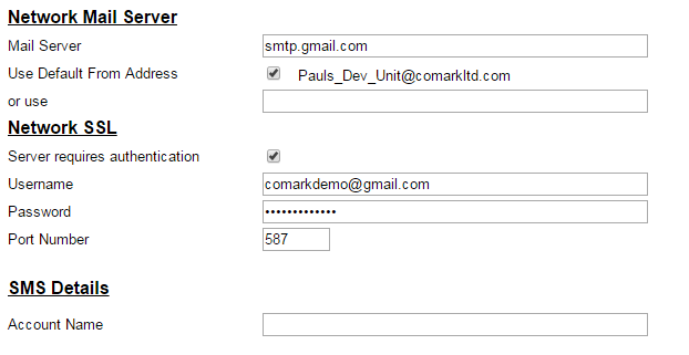
Email Account SetupClick the Administration button then the Setup Emails button then the Email Account button.
Email Account Page Network Mail Server
Network SSL
SMS Details
Network Mail ServerUsually your IT Department will provide the information for this section and whether a custom from address is required. However if you are using an ISPs mail server or web mail service you will find the information required on that company’s support web pages. Due to the proliferation of email spam, many USA based Internet Service Provider (ISP) companies and also web-based email services such as Google and Yahoo require user authentication before allowing emails to be sent using their servers. This authentication is typically performed using SSL encryption which is configured as above. SMS DetailsThe Gateway supports SMS alerts via a third party “Email-to-SMS” conversion service. Comark have tested TextMagic™ (www.textmagic.com). To enable SMS alerts to be sent, subscribe to the TextMagic™ service and configure your account using instructions provided on their website. Other “Email-to-SMS” conversion services may well work with RF500 but are untested. Those providers may require entry of your email address into the Account Name field. | 21st April 2015 | ||||||||||||||||||||||||||||||||||||||||
How do I change the name of a Probe or Transmitter?How do I change the name of a Probe or Transmitter?Changing the name of a Probe or Transmitter can only be achieved by Re-tasking the Transmitter. Please click here for the Knowledgebase Article on Tasking.
| 31st March 2015 | ||||||||||||||||||||||||||||||||||||||||
Setting Time and Date (the Clock) on the GatewaySetting Time and Date (the Clock) on the GatewayHTML or Original InterfaceIn order to change the clock by an hour forward or back, simply visit ‘Administration‘ then the ‘Set Clock‘ option and change the set time accordingly.
You will need to:
On completion of the change, the Gateway will reset. Your Transmitters will synchronise to the new time when they next connect to the Gateway and they will start a new period of data from that new time. No data will be lost during this process. For full instructions on setting the time and date, please refer to the ‘Set Gateway Clock‘ section of the RF500-Webview Help Guide. New 2015 InterfaceIn order to change the clock by an hour forward or back, simply visit ‘Administration – System Settings – Gateway Time‘ to bring up this window…
To set the date and time there are two options to choose from;
On completion of the change, the Gateway will reset. Your Transmitters will synchronise to the new time when they next connect to the Gateway and they will start a new period of data from that new time. No data will be lost during this process. For full instructions on setting the time and date, please refer to the ‘Set Gateway Clock‘ section of the RF500-Webview Help Guide. | |||||||||||||||||||||||||||||||||||||||||
My Gateway does not show any Transmitters only the words ‘Set Clock’My Gateway does not show any Transmitters only the words ‘Set Clock’If your Gateway does not show any Transmitters only the words ‘Set Clock’, then Gateway has lost its date and time. Please click here for the Knowledgebase Article on Setting the Gateway Clock. | |||||||||||||||||||||||||||||||||||||||||
Printing with RF500 GatewaysPrinting with RF500 GatewaysPrinting with RF500 is completed by using the Print function within Internet Explorer or your preferred Browser. However, there is some configuration required, to ensure that screens and colours are displayed correctly. For Internet Explorer (Ver 6)From any page:
Printing in I.E.
For FireFox (Ver 3)From the home page:
Printing in Firefox | |||||||||||||||||||||||||||||||||||||||||
How do I Acknowledge Alarms?How do I Acknowledge Alarms?Alarm AcknowledgeIf you are looking for RF500A Alarm Acknowledge for Version M9, then please click here. When any Transmitter channel with enabled alarms goes into alarm, the Transmitter is said to have an ‘unacknowledged alarm’. Unacknowledged alarms are identified on the Gateway Home Page in three ways:
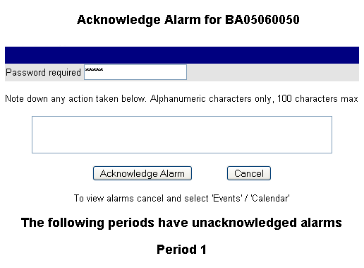
To acknowledge an alarm, navigate to the Transmitter Graph page, Transmitter Tabular Data page or Transmitter Events page. Click on Acknowledge Alarm at the top of the page to bring up the alarm acknowledgement page.
Figure 1 – Alarm Acknowledge All ‘unacknowledged alarms’ for all channels across all Periods are acknowledged together in one operation. You are advised to use the Events Calendar to view the Alarm Events that will be acknowledged by this operation. There could be many. There will be a text box where the reason(s) for the alarm can be entered, along with all actions taken. When you have typed your reason, ensure you have entered your password, before selecting the Acknowledge Alarm button. | 17th June 2015 | ||||||||||||||||||||||||||||||||||||||||
How do I send a copy of the Hardware Settings to Technical Support?How do I send a copy of the Hardware Settings to Technical Support?HTML or Original InterfaceIf you have been asked to send a copy of your Hardware Settings to Comark Technical Support, to assist them with troubleshooting an issue that you are currently experiencing, or simply wish to start an investigation of your Hardware, then simply follow the instructions below:
New 2015 InterfaceIf you have been asked to send a copy of your Hardware Settings to Comark Technical Support, to assist them with troubleshooting an issue that you are currently experiencing, or simply wish to start an investigation of your Hardware, then simply follow the instructions below:
| 31st March 2015 | ||||||||||||||||||||||||||||||||||||||||
How to Sign Historic DataHow to Sign Historic DataSigning of data is a feature of the RF500 Wireless Monitoring System, required for compliance to the electronic signature section of 21 CFR Part 11. From the perspective of 21 CFR Part 11 the definition of an electronic signature is as follows: 12.2.2 Electronic SignatureA computer data compilation, of any symbol or series of symbols, executed, adopted or authorised by an individual to be a legally binding equivalent of the individual’s handwritten signature. Signed data as far as the FDA is concerned means that the signer accepts that the data is true and good, and that he is taking legal responsibility for it. It is no different to printing off the page and signing it with a pen. It can be deemed as legally binding as shown above. As far as RF500 is concerned, each historic Period of Data can be individually signed. A Period cannot be signed if it is still live and capable of storing extra data.
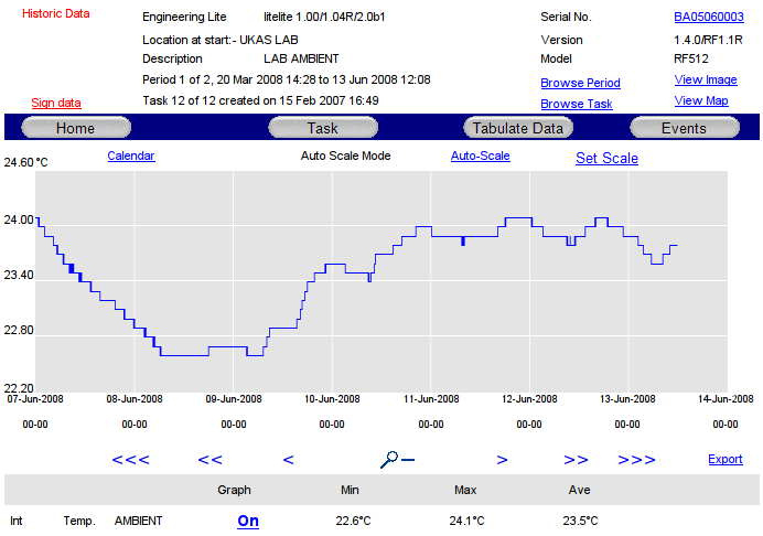
Find Data to Sign
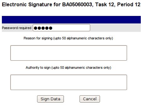
Use the Browse Task and Browse Period links on the Transmitter Graph page, Transmitter Tabular Data page or Transmitter Events page, to find the historic Period to be signed. In order to sign a live Period, that Period must be closed using either Start/Stop Logging or by Tasking the Transmitter. Only once it has become historic it is possible to sign the data. To sign data, click the Sign Data link and the following page will be displayed:
Finding Data to Sign
To sign data, enter the reason for signing the data and your authority to sign, enter your password and click the Sign Data button. The data is then digitally signed and the text entered is displayed on the Transmitter Graph page, Transmitter Tabular Data page and Transmitter Events page. Each action of Data Signing is recorded in the Audit Trail. | |||||||||||||||||||||||||||||||||||||||||
When I try to ‘Acknowledge’ or ‘Snooze’ an alarm I get an unexplained errorWhen I try to ‘Acknowledge’ or ‘Snooze’ an alarm I get an unexplained errorIf there is any error on the Gateway when ‘Acknowledging’ or ‘Snoozing’ an alarm, that cannot be explained, then we urge you to contact us, advising us of this problem. | |||||||||||||||||||||||||||||||||||||||||
Unable to ‘Task’ a Transmitter due to an unexplained errorUnable to ‘Task’ a Transmitter due to an unexplained errorIf there is any error on the Gateway when tasking a Transmitter, that cannot be explained, then we would urge you to contact us, advising us of this problem. | |||||||||||||||||||||||||||||||||||||||||
My Audit Trail has some corruptionMy Audit Trail has some corruptionIf the following appears in the Audit Trail of your RF500 System Gateway.
Then we would urge you to contact us, advising us of the problem details.
| |||||||||||||||||||||||||||||||||||||||||
Where do I find the data from Transmitters that have been removed/replaced?Where do I find the data from Transmitters that have been removed/replaced?RF500 System Transmitters fall into two Categories;
This article will explain how to view Historic Data for removed Transmitters.
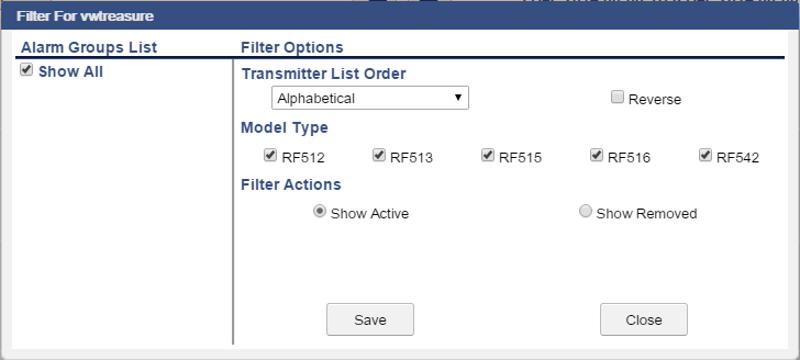
HTML or Original InterfaceIf you have recently removed or replaced Transmitters on your RF500 System, but still wish to access their Data, then you simply need to navigate to your RF500 System Gateway ‘Home‘ page and select ‘My Preferences‘. Once that page loads, go to the ‘Filter‘ options and select ‘Show Removed‘ and then click on the ‘OK’ button. If you then click the Transmitter name, or the graph window, you will open the Transmitter summary. Here you can select ‘Calendar‘ to view all available dates that have data from that Transmitter. Simply click on a specific calendar date to view the historic data for that date. New 2015 InterfaceIf you have recently removed or replaced Transmitters on your RF500 System, but still wish to access their Data, then you simply need to login to your RF500 System Gateway click on your username top left and select ‘My Filter‘. From the window that opens under Filter Actions select Show Removed, see picture.
Select Save to save and close. Your Gateway will now show you the Removed Transmitters instead of the current Active Transmitters. Simply navigate as you would for the current transmitters. Remember to undo the My Filter settings to see the current data. Note: While viewing Historic Data for Removed Transmitters all your current Active Transmitters will still be sending in their data.
| |||||||||||||||||||||||||||||||||||||||||
Do I have the latest Gateway Software Version installed?Do I have the latest Gateway Software Version installed?In order to ascertain which version of the Software your Gateway is running, you will need to check by logging on to your Gateway and navigating to the ‘Hardware’ page. HTML or Original Interface
New 2015 Interface
The following table explains the various Software versions that have been installed on RF500A Gateways since their launch in 2011:
For further information on upgrading the Software of your RF500 System Gateway Software please read this related knowledge base article. | |||||||||||||||||||||||||||||||||||||||||
Does the RF500 Gateway adjust for Daylight Saving Time?Does the RF500 Gateway adjust for Daylight Saving Time?Unfortunately, the RF500A/RF500AP Gateway does not have a built-in feature to automatically adjust the internal clock when it comes to Daylight Saving Time (DST) adjustments. The clock will therefore need to be adjusted manually. HTML or Original InterfaceIn order to change the clock by an hour forward or back, simply visit ‘Administration’ then the ‘Set Clock’ option and change the set time accordingly.
You will need to:
On completion of the change, the Gateway will reset. Your Transmitters will synchronise to the new time when they next connect to the Gateway and they will start a new period of data from that new time. No data will be lost during this process. For full instructions on setting the time and date, please refer to the ‘Set Gateway Clock‘ section of the RF500-Webview Help Guide. New 2015 InterfaceIn order to change the clock by an hour forward or back, simply visit ‘Administration – System Settings – Gateway Time‘ to bring up this window…
To set the date and time there are two options to choose from;
On completion of the change, the Gateway will reset. Your Transmitters will synchronise to the new time when they next connect to the Gateway and they will start a new period of data from that new time. No data will be lost during this process. For full instructions on setting the time and date, please refer to the ‘Set Gateway Clock‘ section of the RF500-Webview Help Guide. | |||||||||||||||||||||||||||||||||||||||||
How do I perform a Task and Data Retrieve?How do I perform a Task and Data Retrieve?A ‘Task and Data Retrieve’ command is usually requested when there is a reason for a GAP to have appeared in the Data. This can be as a result of re-building your Gateway from a recent Manual Backup, for example. The ‘Task and Data Retrieve’ command will attempt to recover all data from the Transmitter, including Task information and all alarms occurring for the period in question. Please note however, that during the retrieve process all historic alarms will re-occur on the Gateway and will need to be acknowledged in the normal way. It is therefore recommended that you inform other users that Alarm E-mails will be resent during the process. The process itself can take several hours to complete, depending on the amount of data being retrieved, however the Transmitter will continue to log normally during this period, but new alarms will not be sent until the old data is up to date. Once the process is complete you will have a ‘Retrieved Task’ on your Gateway in the Transmitter Task History and the data pertaining to that Task. A new data period will be started when all the data has been recovered. To complete the Task and Data Retrieve navigate to the Transmitter Summary from the Home Page and click on the Serial No, top right hand corner of the screen. Then click Edit. From there tick the the box ‘Retrieve Task & Data’, enter your password into the box in the top bar and click Edit to finish. Note: When completing Task and Data Retrieve it is important to be congnisant of the number of transmitters and also the relative mix of Meshing Transmitters vs Battery Only Transmitters. In either case though, it is important to start with the meshing units as these are always on and while they are completing their Task and Data Retrieve the responsiveness of the whole system can be compromised. So, identify the Meshing units and complete Task and Data Retrieve on these first. During this process the other Transmitters in the system will continue to log normally. When the meshing units are complete then you can start to batch up the rest of the battery only units. Irrespective of the remaining number of transmitters it is advised to complete the process Location by Location and if more than 5 transmitters in any single location, only complete the task on 5 at a time. if in any doubt contact technical support for advice’ | 24th March 2015 | ||||||||||||||||||||||||||||||||||||||||
Why am I seeing incorrect dates in the Audit Trail?Why am I seeing incorrect dates in the Audit Trail?If you are seeing incorrect or spurious dates in the Audit Trail of your RF500A/RF500AP Gateway device, then you should initially check the date and time settings on your Gateway. Should you notice that the date of your Gateway device is set to ‘Jan 1 1970’ we would initially advise setting it to the correct date. Should the problem re-occur, then we would urge you to contact us, advising us of this problem.
| |||||||||||||||||||||||||||||||||||||||||
Why am I unable to download/create a Manual Back-Up?Why am I unable to download/create a Manual Back-Up?If you are unable to download or create a manual back-up from your RF500 System Gateway device, then initially we would suspect this to be down to a localised PC or Local Area Network (LAN) issue. Please refer to your internal IT Administrator or department for further advice and guidance. If you have ruled out a localised PC or Local Area Network (LAN) issue and are still unable to download or create a manual back-up, then we would urge you to contact us directly for further troubleshooting and advice. | |||||||||||||||||||||||||||||||||||||||||
Why is my Audit Trail showing ‘Cipher Host Reset’?Why is my Audit Trail showing ‘Cipher Host Reset’?The ‘Cipher Host Reset’ listing is a reference to an internal function of the Gateway. It is usually nothing to worry about, however, if your Gateway is showing such listings on a regular and repeat basis i.e. more than once or twice per month then we would suggest that you contact us so that we can investigate the situation further for you. | |||||||||||||||||||||||||||||||||||||||||
How do I send a copy of my Audit Trail to Technical Support?How do I send a copy of my Audit Trail to Technical Support?If you have been asked to send a copy of your Audit Trail to Comark Technical Support, to assist them with troubleshooting an issue that you are currently experiencing, or simply wish to start an investigation of your Audit Trail, then simply follow the instructions below:
| |||||||||||||||||||||||||||||||||||||||||
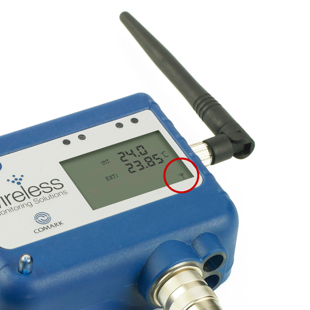
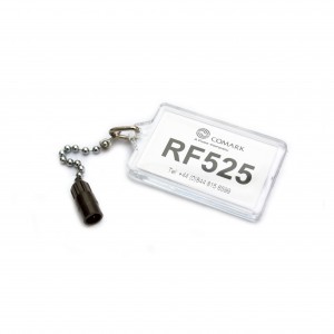
Why does my Transmitter flash the antenna symbol three times when Activator used?Why does my Transmitter flash the antenna symbol three times when Activator used?On occasion you may find that one of your RF51x Transmitters will not communicate with your RF500 System Gateway device and when you attempt to ‘provoke’ the Transmitter using the RF525 Transmitter Activator, the small ‘antenna’ symbol (shown below) just flashes three times.
This will potentially happen if the Transmitter in question believes that it is a Meshing (or Backbone) Unit. In which case, it will not communicate with the Gateway unless it is connected to an external Power Supply Unit (RF520).
Ensure that the RF520 Power Supply Unit is connected to the Transmitter and powered on, then try to ‘provoke’ the Transmitter once more, using the RF525 Transmitter Activator. If the Transmitter is not meant to be a Meshing or Backbone Unit then ensure that it is not set to be a ‘Backbone’ Unit on the Gateway. Confirm that this change has gone through on the Gateway before removing power from the Transmitter and re-installing. | 18th March 2015 | ||||||||||||||||||||||||||||||||||||||||
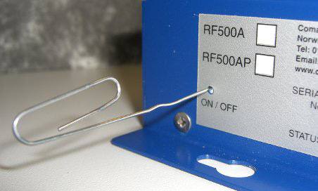
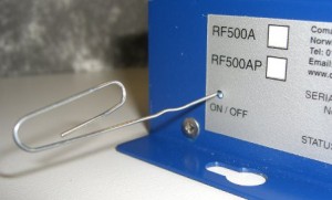
How do I turn my RF500A Gateway Device on/off?How do I turn my RF500A Gateway Device on/off?Turning your RF500A Gateway onTo turn your RF500A Gateway Device on, ensure that it is plugged in initially, using the Gateway AC adapter (supplied). This should be inserted into the socket on the underside of the Gateway (RF500A). For the PoE model of the Gateway (RF500AP) simply plug the Ethernet cable into a PoE enabled network socket. At this stage, the ‘Power/Battery’ indicator LED should be steady green. Using a paperclip or similar object, press in and hold the ‘ON/OFF’ switch on the side of the Gateway (see below) until an audible beep is heard from the Gateway. This should take approximately 3-4 seconds. Once the beep has been heard release the button by removing the paperclip.
The Gateway will beep once and the blue ‘ON’ indicator will flash at a half-second interval. The Gateway boot-up will then begin. This will take up to 5 minutes to complete. On successful boot, the ‘ON’ indicator should remain a solid blue. During the start-up process there will be a series of beeps. Initially you should hear two beeps, followed by four consecutive beeps. It is only after you have heard the four consecutive beeps that you will be able to log onto to your Gateway device.
Turning your RF500A Gateway offThere are in fact two methods for turning off your RF500A Gateway device. You can physically turn your RF500A Gateway Device off using a paperclip or similar object. Simply press in and hold the ‘ON/OFF’ switch on the side of the Gateway (see above) until an audible beep is heard from the Gateway. This should take approximately 3-4 seconds. Once the beep has been heard release the button by removing the paperclip. The Gateway will then begin its shutdown process, which can take up to five minutes to complete. Once complete the blue ‘ON’ indicator will no longer be illuminated. You could also issue a shutdown command from within the software. Simply navigate to the Gateway ‘Hardware’ page and select ‘Shutdown’. You will need to enter an Administrator Password to perform this action.
| 27th January 2015 | ||||||||||||||||||||||||||||||||||||||||
Why does my Gateway data show as ‘—X—X—‘?Why does my Gateway data show as ‘—X—X—‘?Your RF500 System Gateway will show data as ‘—X—X—‘ if you have had Probes/Sensors disconnected from Transmitters for a short time. Your Gateway will display the correct data once the Probes/Sensors in question have been reconnected, though there might be a short delay. The ‘—X—X—‘ listing appears if data is missing, based on the current time window. The default time window presented on the home screen is today’s date, from midnight to midnight. As no temperature record was taken during the time the Probes/Sensors were disconnected, the home page values will be incomplete. The Gateway will not be able to clear the ‘—X—X—‘ listing, because the default view of today includes a missing link in the data. Minimum, maximum and average value sets are incomplete. If the probes are left intact you’ll begin having accurate calculations on the home screen once again, after midnight. Should you need this information, then there are two ways in which it can be calculated: Firstly, you can click on the Graph to get into the Transmitter summary using the ‘zoom’ tool to move ONLY the time before the disconnect into view. At that point you should see accurate calculations below the graph. You can repeat the same procedure for calculations occurring after the disconnect and combine the two. Secondly, the tabular report will show all records that were actually collected before and after the disconnect. You can either export, or copy and paste this Data to Excel. The faulty readings can then be removed and you are then free to perform your own calculations on the columns. | 19th November 2014 | ||||||||||||||||||||||||||||||||||||||||
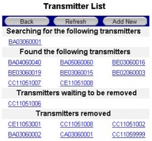
How do I add a new Transmitter to my Gateway?How do I add a new Transmitter to my Gateway?To add a new Transmitter to your existing RF500 Gateway device, simply follow the instructions below, or refer to the ‘Transmitter Management’ section of the in the RF500 Webview Help Guide (Pages 46-47). Transmitter settings are usually only able to be accessed by a System ‘Administrator’, although the permissions required to add a new Transmitter, can be granted to a ‘Restricted User’. To add a new Transmitter you should navigate to the Gateway Home Page, click the ‘Administration’ button, followed by the ‘Transmitters’ button. A categorised list of Transmitter Serial Numbers will then be displayed (as below), along with the option to ‘Add New’.
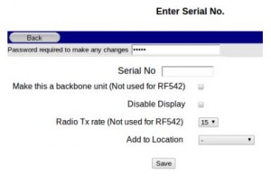
Click on the ‘Add New’ button (as shown above) after which you should get a form, similar to that shown below;
You will need to enter the following information to add a new Transmitter:
Once you have entered that information and decide on the other options you require, simply click on the ‘Save’ button. Your newly added Transmitter should now appear in the section entitled ‘Searching for the following Transmitters’.
| |||||||||||||||||||||||||||||||||||||||||
My Gateway cannot find a newly added TransmitterMy Gateway cannot find a newly added TransmitterIf you have recently added a new Transmitter to your Gateway and the Transmitter in question remains stuck in the ‘Searching for the following Transmitters’ section (as shown below), then you should follow the advice, as outlined below.
Firstly, confirm that you have ‘activated’ the Transmitter in question and that it is ‘awake’. Secondly, confirm that you are in range of the Gateway device and, if necessary, move the Transmitter closer to the Gateway. We would also advise that you double-check that the Transmitter Serial Number was entered correctly. The last thing to check would be the Transmitter itself, to see if an ‘Error’ or ‘Fault’ message is displayed. For a full list of ‘Error’ and ‘Fault’ messages, see the following articles:
| |||||||||||||||||||||||||||||||||||||||||
Why is my Gateway beeping?Why is my Gateway beeping?The RF500 System Gateway will emit an audible alarm or beep to alert you to the following conditions:
Boot-up and power down are considered normal operation, the beeping will stop as soon as the process involved is complete. If your RF500 System Gateway starts beeping in normal operation, then we would recommend that you log on to your Gateway as soon as possible to check the ‘Homepage’ for a Transmitter Alarm Message that may be present. If you discover an Alarm Message, then you should navigate to the Transmitter that is issuing the ‘Alarm’ and ‘Acknowledge’ or ‘Snooze’ that Alarm. You should then take the appropriate action to rectify the original cause of the alarm.
| |||||||||||||||||||||||||||||||||||||||||
My Gateway isn’t E-Mailing me NotificationsMy Gateway isn’t E-Mailing me NotificationsIf E-mails stop working, or you believe that the Gateway has stopped sending e-mails, it is important to ask swiftly but methodically to identify the source of the problem. If the Gateway as only recently been set-up, please check that all of the e-mail addresses entered as valid, as one invalid e-mail can prevent all subsequent e-mails from being sent. Are e-mails working on your PC and your colleagues around you? If no then please contact your IT to help diagnose the problem as it may not be related to the Gateway. If e-mails are working normally on your PC then we need to look a little further into the Gateway(s) to find out what’s going wrong. Log on to your Gateway(s) and check the following:
If you continue to have problems please contact us for further assistance.
| |||||||||||||||||||||||||||||||||||||||||
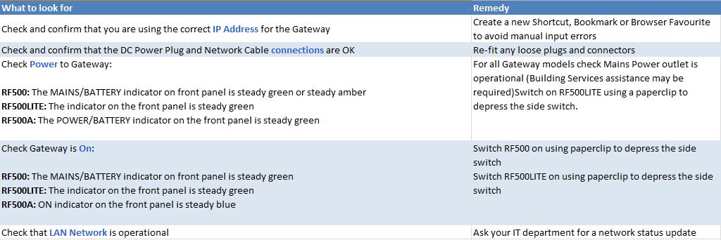
Cannot Access Gateway / Loss Of Connection To GatewayCannot Access Gateway / Loss Of Connection To GatewayIf you cannot connect to or access your RF500A or RF500AP Gateway device, or you used to be able to connect to it but have lost connection recently, then the following troubleshooting information should help:
| 18th November 2014 | ||||||||||||||||||||||||||||||||||||||||
Low battery indicated but battery voltage still showing high levelLow battery indicated but battery voltage still showing high levelThe lithium batteries used in Transmitters are very useful for their high performance and long life, especially at low operating temperatures. However, monitoring their end of life is difficult. For this reason RF500A/RF500AP Gateway device will latch a battery low warning as soon as one is recorded. It it important not to ignore the low battery warning and change the battery as soon as possible. A battery that is near end of life will show a reduced battery level during high load conditions, if this high load is reduced, the battery will recover over time and indicate a high battery level once more. We would recommend that you change the battery as soon as you receive the ‘Low Battery’ warning. If the low battery returns very quickly with the new battery fitted please contact Comark for further advice. | |||||||||||||||||||||||||||||||||||||||||
Low battery indication does not clearLow battery indication does not clearThe ‘Low Battery’ message on the homepage of the Gateway might not clear immediately after you have changed the battery of one of your transmitters.
When a Transmitter battery is replaced, it generates a ‘Battery Good’ event record and queues it for transmission to the Gateway. The ‘Low Battery’ message on the Homepage of the Gateway is cleared when the Gateway receives this ‘Battery Good’ record from the Transmitter. This event record is also posted to the Audit Trail as pictured below.
The Transmitter data queue could be several thousand records long and may take several hours before the ‘Battery Good’ record is sent. You can check this progress by looking for the last data on the homepage of the Transmitter. When the data is up-to-date then the ‘Low Battery’ warning should also clear. The best way to avoid this delay is to change the battery soon after the first ‘Low Battery’ warning message is posted on the Gateway homepage. The longer the Transmitter is left in the low battery condition the longer the data record queue becomes. Beware of re-tasking the Transmitter, because the data record queue is cleared as a result. The ‘Battery Good’ record will also be cleared and the Gateway ‘Low Battery’ message will not clear even through the Transmitter appears to be working normally. Should this happen, then simply remove and refit the battery of the Transmitter in question, so that the Transmitter believes that a new battery has been fitted.
| |||||||||||||||||||||||||||||||||||||||||
Gateway fault conditions explainedGateway fault conditions explainedUnder certain conditions the amber coloured Gateway ‘Fault’ LED can flash to indicate an error. The possible faults which can cause the ‘Fault’ LED to flash are as follows:
| |||||||||||||||||||||||||||||||||||||||||
RF500A QSG – Gateway Tabular View/Printable Version for Comark RF500A Issue M9RF500A QSG – Gateway Tabular View/Printable Version for Comark RF500A Issue M9Tabular ViewTabular View presents one days’ worth of data in tabular format, for the purposes of review and reporting, It also includes the option for a printable report. This screen displays data for the currently selected day in tabular form.
Figure 1 – Transmitter TAB View The Transmitter TAB View has the following:
1. The CalendarThe Tabular view of the selected Transmitter defaults to the last date in the current selection, e.g. to-day. If you wish to see tabular data for any other date simply use the Calendar to select another day, date selection or month. 2. Move Forward-BackClicking 3. Drop DownUse the Drop Down to select a different Transmitter or just a previous Task or Period. Once the selection has been made the Tabular data will re-populate based on the new selection. 4. Printable VersionTo ensure repeatability when printing we have added a printable version button to this TAB View. Simple click
Figure 2 – Tabular Report
Additional information is provided with the report, including details of the Transmitter and the Gateway. Transmitter Tabular Data – Record Colouring
Other error conditions, black text over yellow background
Transmitter Tabular Data – Door ReadingsThe readings reported for the door channel are given as two values:
| 11th August 2015 | ||||||||||||||||||||||||||||||||||||||||
What happens to my RF500 System in the event of a mains power failure?What happens to my RF500 System in the event of a mains power failure?In the event of a mains power failure, a failure of the AC mains power adapter, or a PoE power supply, your Gateway device will continue to work as normal for the following durations:
During this time however, it should be noted that your network might not be operational and therefore you might not be able to log on to your Gateway during this time. Backbone Transmitters will also continue to work. The battery life of a Backbone Transmitter, whilst just on battery power is up to 4 days in total. It should be noted that Backbone Transmitters running version 3.0.0 Firmware or higher, will operate under battery power for just 1 hour at a time. This is to prevent unnecessary use of the battery after the RF500 Gateway has switched off. Should an alarm go off during the power outage and you have an RF523 Auto Dialer, then so long as the battery backup is working, this too will continue to work and will try to send phone messages accordingly. This is of course subject to the phone line being operational.
| 18th November 2014 | ||||||||||||||||||||||||||||||||||||||||
How do I upgrade the Software of my RF500 Gateway Device?How do I upgrade the Software of my RF500 Gateway Device?The following instructions are designed to assist you, should you wish to upgrade the Software of your RF500A/RF500AP Gateway Device or the RF500 Backup Server Software (if applicable). Before you startIn order to perform the upgrade you must be logged on to your PC as an Administrator. The update process will only take a few minutes from start to finish. However please be aware that your system could take a couple of hours for the transmitters to recover communication. Therefore you may choose to perform this update overnight, hence by the following morning the system will be back to normal. During the update process and for the short time afterwards although no data will be lost, the Gateway will not be up to date and therefore alarms may be missed during this time. If there are other people logging on to the Gateway from other locations it is a good idea to let them know that the Gateway will not be available for a few minutes. Also if the Gateway is not local to you when performing the Update it will beep a number a times during the update process so local users should be made aware that this is OK. What if my system is Validated?If your RF500 system is validated by means of IQ OQ PQ, then you are advised to satisfy yourself what further re-validaiton of the system might be necessary before performing the upgrade. You may choose therefore, not to perform the upgrade. However, under certain circumstances Comark will advise that the update is necessary and therefore an amount of re-validation will be inevitable to maintain the health of the system. If in doubt please contact Comark for more information. Ready to update?Log on to the Gateway as an Administrator and navigate to Upgrade Firmware page by selecting Administration and then Upgrade Firmware buttons. This will bring up the firmware update page…
The latest version of the RF500 System Gateway software is available here.
| 24th March 2015 | ||||||||||||||||||||||||||||||||||||||||
How do I reset my RF500 Gateway Device?How do I reset my RF500 Gateway Device?You can reset your RF500A/RF500AP Gateway Device using one of two methods. Manual Reset MethodAssuming that the Gateway Device is powered on, you can physically turn your RF500A Gateway Device off using a paperclip or similar object. Simply press in and hold the ‘ON/OFF’ switch on the side of the Gateway (see below) until an audible beep is heard from the Gateway. This should take approximately 3-4 seconds. Once the beep has been heard release the button by removing the paperclip.
The Gateway will then begin its shutdown process, which can take up to five minutes to complete. Once complete the blue ‘ON’ indicator will no longer be illuminated. Using a paperclip or similar object, press in and hold the ‘ON/OFF’ switch on the side of the Gateway (see below) until an audible beep is heard from the Gateway. This should take approximately 3-4 seconds. Once the beep has been heard release the button by removing the paperclip. The Gateway will beep once and the blue ‘ON’ indicator will flash at a half-second interval. The Gateway boot-up will then begin. This will take up to 5 minutes to complete. On successful boot, the ‘ON’ indicator should remain a solid blue. During the start-up process there will be a series of beeps. Initially you should hear two beeps, followed by four consecutive beeps. It is only after you have heard the four consecutive beeps that you will be able to log onto to your Gateway device. Software Reset MethodYou can also issue a reset command from within the software. Simply navigate to the Gateway ‘Hardware’ page and select ‘Reset’. You will need to enter an Administrator Password to perform this action. | 16th June 2014 |
Related products
- RF524
%22%20transform%3D%22translate(.8%20.8)%20scale(1.5625)%22%20fill-opacity%3D%22.5%22%3E%3Cellipse%20fill%3D%22%23ad0400%22%20rx%3D%221%22%20ry%3D%221%22%20transform%3D%22matrix(-3.77105%2078.75267%20-54.4553%20-2.60758%20121.2%20121.3)%22%2F%3E%3Cellipse%20fill%3D%22%23fff%22%20cx%3D%22226%22%20cy%3D%22136%22%20rx%3D%2244%22%20ry%3D%22255%22%2F%3E%3Cellipse%20fill%3D%22%23fff%22%20rx%3D%221%22%20ry%3D%221%22%20transform%3D%22matrix(12.46863%20254.69498%20-72.7197%203.56%209%20165)%22%2F%3E%3Cellipse%20fill%3D%22%23c4370c%22%20rx%3D%221%22%20ry%3D%221%22%20transform%3D%22matrix(-35.80315%203.69048%20-6.6183%20-64.20731%20119.9%20120)%22%2F%3E%3C%2Fg%3E%3C%2Fsvg%3E)
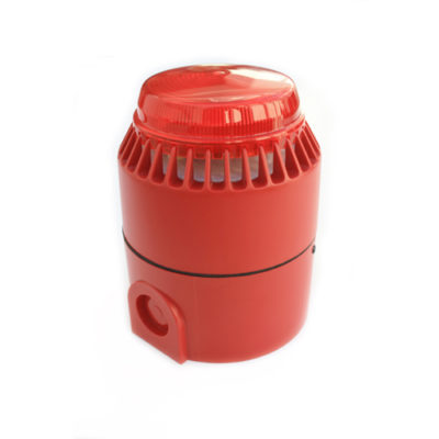
Siren Beacon
- RF523
%27%20fill-opacity%3D%27.5%27%3E%3Cellipse%20fill%3D%22%23cecece%22%20fill-opacity%3D%22.5%22%20rx%3D%221%22%20ry%3D%221%22%20transform%3D%22matrix(-35.37201%2087.5488%20-152.8229%20-61.74446%20188.3%20188.8)%22%2F%3E%3Cpath%20fill%3D%22%23fff%22%20fill-opacity%3D%22.5%22%20d%3D%22M-13.3%20413.3l407.8-14L-24.2%20182z%22%2F%3E%3Cellipse%20fill%3D%22%23fff%22%20fill-opacity%3D%22.5%22%20rx%3D%221%22%20ry%3D%221%22%20transform%3D%22rotate(-170.2%20145%2012.2)%20scale(372.47029%2067.6971)%22%2F%3E%3Cellipse%20fill%3D%22%23fff%22%20fill-opacity%3D%22.5%22%20rx%3D%221%22%20ry%3D%221%22%20transform%3D%22matrix(-65.47425%20387.28683%20-61.9634%20-10.47546%20399.2%20249.2)%22%2F%3E%3C%2Fg%3E%3C%2Fsvg%3E)
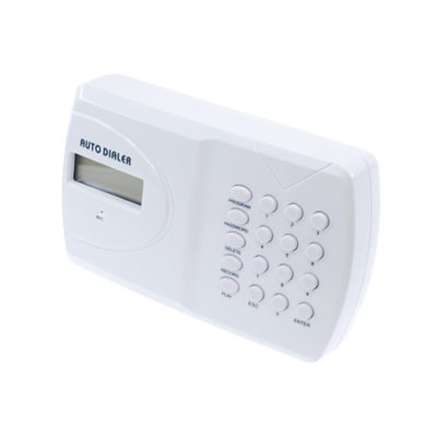
Autodialler
- RF504
%22%20transform%3D%22translate(.8%20.8)%20scale(1.5625)%22%20fill-opacity%3D%22.5%22%3E%3Cellipse%20fill%3D%22%23ccc%22%20rx%3D%221%22%20ry%3D%221%22%20transform%3D%22rotate(4.6%20-1576%201641.5)%20scale(37.72522%20125.10825)%22%2F%3E%3Cellipse%20fill%3D%22%23fff%22%20cx%3D%22224%22%20cy%3D%2296%22%20rx%3D%2262%22%20ry%3D%22255%22%2F%3E%3Cellipse%20fill%3D%22%23fff%22%20rx%3D%221%22%20ry%3D%221%22%20transform%3D%22matrix(-5.34032%20254.94407%20-63.44056%20-1.32889%2029.1%2082.9)%22%2F%3E%3Cellipse%20fill%3D%22%23fff%22%20rx%3D%221%22%20ry%3D%221%22%20transform%3D%22matrix(37.18695%20-8.51695%2049.53581%20216.2847%20197.5%2060.7)%22%2F%3E%3C%2Fg%3E%3C%2Fsvg%3E)
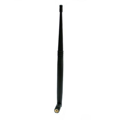
High Gain Antenna
- RF500APSU
%27%20fill-opacity%3D%27.5%27%3E%3Cellipse%20fill%3D%22%23555%22%20fill-opacity%3D%22.5%22%20rx%3D%221%22%20ry%3D%221%22%20transform%3D%22matrix(21.56441%20150.51804%20-64.36158%209.22095%20195.8%20221.8)%22%2F%3E%3Cpath%20fill%3D%22%23fff%22%20fill-opacity%3D%22.5%22%20d%3D%22M332.6%20398L229.5%2013.3l164.5-44L497%20354z%22%2F%3E%3Cellipse%20fill%3D%22%23fff%22%20fill-opacity%3D%22.5%22%20rx%3D%221%22%20ry%3D%221%22%20transform%3D%22rotate(176.7%2019.8%20105.7)%20scale(62.84614%20398.43752)%22%2F%3E%3Cpath%20fill%3D%22%23737373%22%20fill-opacity%3D%22.5%22%20d%3D%22M107.2%20257l107.1-47.7%2039.4%2088.5-107%2047.6z%22%2F%3E%3C%2Fg%3E%3C%2Fsvg%3E)
RF500A Mains PSU


