Transmitter Task
Data cannot be collected from a Transmitter until a Task has been programmed. To create a new Task, click the Task button on the Transmitter Graph Button Bar. The Transmitter Task page will appear.
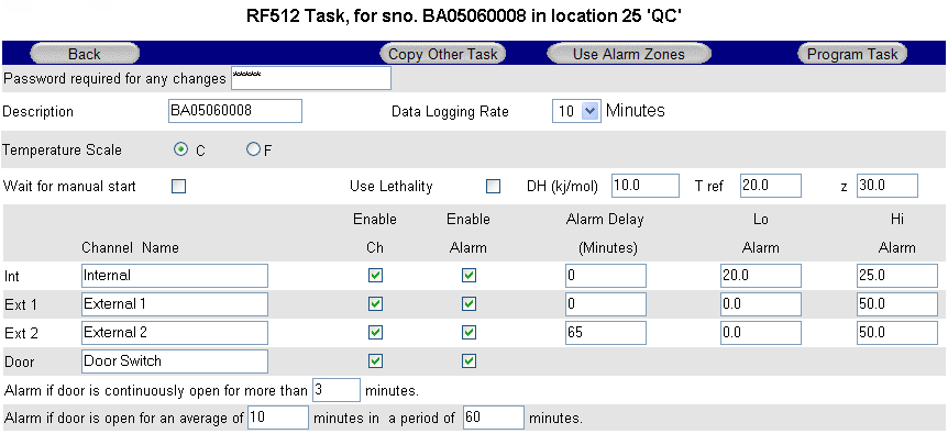
Transmitter Task
- Description Up to 16 characters available to describe transmitter, e.g. transmitter Location.
- Enable Ch Enable or disable individual channels.
- Enable Alarm Enable alarm limits for individual channels.
- Channel Name Text box to identify each channel. (Up to 23 characters available)
- Use Lethality/mkt See Mean Kinetic Temperature and Lethality.
- Temperature Scale Choose °C or °F as required.
- Humidity Scale Choose %rh or dew point as required.
- Log rate Selection of log rate – available log rates: 1, 2, 3, 5, 10, 15, 20, 30, 60 minutes.
- Note: log rate of less than 15 minutes will reduce battery life.
- Wait for Manual Start If this box is ticked then the transmitter will not automatically start logging and must be started manually See Start / Stop Logging.
- Alarm Delay Set alarm time delay, e.g. for defrost cycle.
Transmitter Task – Button Bar
Copy Other Task Link to copy Tasks from other transmitters of same model for quick programming.
Use Alarm Zones See Dynamic Alarms below.
Program Task Enter your password and click to send new Task to transmitter.
Transmitter Task – Tasking
Once the Program Task button is clicked, the Daily Readings Summary on the Gateway Home Page will indicate No Data and qT to indicate Tasking. It can take several minutes for the Task to be sent to the transmitter because the Gateway must first wait for the transmitter to contact it.
Transmitter Task – RF515
The Task page for RF515 deserves special mention because it is very different from other transmitters, in that this page caters for both regular task setup and also configuration of scale mapping between analog units and engineering units of the sensor.

Task Setup for RF515
Sensor Type Select the option to match the sensor output
- 0V to 1V
- 0V to 10V
- 4mA to 20mA
Units Engineering units for sensor (Up to 8 characters available)
Decimal Places The number of decimal places required for engineering units (0 to 5)
Display xxxxx as yyyyy These 2 sets of numbers define the scale mapping between measured units (V or mA) and sensor units. The example for Ext1 shows 4-20mA mapping to 0-100%RH Lo Alarm & Hi Alarm Alarm limits are entered using engineering units for the sensor.
The allowable range of values for yyyyy in the Display xxxxx as yyyyy field and also in Lo Alarm & Hi Alarm depends on the number of decimal places selected. See the table below.
Decimal Places Range
- 0 ±32000
- 1 ±3200.0
- 2 ±320.00
- 3 ±32.000
- 4 ±3.2000
- 5 ±0.32000
Transmitter Alarms
The graph below shows a temperature profile for a transmitter tasked for 15 minutes log rate, the High Alarm at 5.0 and Low Alarm at 1.0, and 5 minute alarm delay.

Transmitter Alarms
- >
- The curve indicates the actual temperature being sampled by RF500.
- The small dots indicate the sampling at 1 minute intervals.
- The large black dots indicate readings logged at 15 minute (log rate) intervals.
- When the temperature goes out-of-limit, extra records are logged as indicated by the blue dots as follows:
- A The record logged as the temperature goes out-of-limit (high)
- B The record logged because the temperature has remained out-of-limit
throughout the alarm delay - C The maximum temperature reached for the out-of-limit period
- D The record logged as the temperature again becomes within limits
- E The record logged as the temperature goes out-of-limit (low)
- F The minimum temperature reached for the out-of-limit period
- G The record logged because the temperature has remained out-of-limit
throughout the alarm delay - H The record logged as the temperature again Low Alarm becomes within limits
Points B and G correspond to data records which generate alarm Events. They cause the transmitter to have an unacknowledged alarm which in turn generates alerts according to the Location in which the transmitter is placed. These alarm Event records are shown as entries in the Transmitter Events Page and in the Audit Trail.
Door Alarms
RF500 includes two types of Door Alarm:
Continuous Door Alarm – Alarm on Door continuously open for a period of more than X minutes
Average Door Alarm – Alarm on Door open for more than X minutes cumulatively in a given period of up to 60 minutes. This alarm captures many individual shorter door open times that may fail to trigger a continuous door alarm but are nonetheless still important.
 | Both continuous and average door alarms are enabled or disabled together, therefore if the average door alarm is not required, setting the average limit equal to the average period causes the average alarm never to occur because the limit can not be exceeded. |
| Whenever a continuous door alarm is triggered an Event only is generated, tabular data will not be coloured to indicate the alarm. |
Date / Time Fence Gate
01 Jul 2010 08:07 25.7 °C 12 (32.19%)
A representation of tabular data shown above shows a typical reading. The readings reported for the door channel are given as two values:
- The first number is the cumulative number of minutes that the door has been open throughout the averaging interval, which in this example, is the preceding 60 minutes.
- The value in parentheses is the cumulative number of minutes that the door has been open throughout the averaging interval given as a percentage of the averaging interval.
The percentage gives a measure of how much time a door actually spends opened which could represent a problem in a real world application. Consider the following scenario:
A door to a laboratory is monitored using RF500 and the continuous alarm is set to 20 minutes to capture a “door left open” event. If that door is opened then closed after 19 minutes have elapsed, then immediately opened again for 19 minutes then closed, the continuous alarm event would not have been generated; however that door has effectively been open for 38 minutes during the previous 40 minutes or so. With an averaging interval of 60 minutes the RF500 system would report a door reading of approximately 63% or with an averaging interval of 40 minutes a door reading of close to 100% would be reported. It may be the case that this high level of “door open” condition may cause environmental controls to be overloaded.
Dynamic Alarms
Dynamic alarms allow the transmitter to vary the alarm limits or indeed disable alarms for each 30 minute time-slot throughout a 7-day period. Typical uses for this feature include cycling incubators which cycle between temperatures and chillers which are only active for certain times during the week.
From the Task Setup page, click the Use Alarm Zones button to activate this function. The fixed alarm limits for each channel are replaced by Dynamic Times buttons. For each enabled channel, click the Dynamic Times button to configure the alarm limits for each time-slot of the 7-day period.

Dynamic Alarm Setup
Each cell represents the alarm limits for a 30 minute time slot the first beginning at midnight 00:00 and the last beginning at 23:30. Enter up to four sets or zones of alarm limits as required. To allocate an alarm zone to each cell first click the Slot coloured block to the left of the alarm zone then click the cell to allocate to the selected zone. The area above the M representing Monday, shows which alarm zone has been selected.
(In the Figure above the 20.0 to 40.0 zone has been selected and the cell for Tuesday 12:30 is about to be clicked yellow.)
To quickly set the entire grid to one alarm zone click the Set All colour to the right of the chosen alarm zone.
When done click the OK button on the button bar.
Dynamic Alarms for Door Switch
Setup of dynamic alarms for Door Switches is as per temperature or RH channels except only the average alarm limit for Door can be changed dynamically, the continuous alarm limit remains in effect at all times.