- Sorry, this product cannot be purchased.

RF542 Remote Temperature Monitor
Part No: RF542/UK (4177861)The RF542 Remote Temperature Monitor connects via a port to LAN or WAN anywhere so you can expand your RF500 Wireless Monitoring System using your existing network.
- Temperature Range: -40°F to +257°F / -40°C to +125°C
- 24/7 Email and SMS Alerts
- Selectable scales °C/°F
- Warranty: 2 Years

Remote Temperature Monitor
The RF542 Remote Temperature Monitor connects via a port to LAN or WAN anywhere so you can expand your RF500 Wireless Monitoring System using your existing network.
The RF542 can monitor two temperature points from up to 64 different locations using one Gateway!
- LCD screen for local temperature display at point of measurement
- 24/7 Email and SMS Alerts
- Selectable scales °C/°F
- BioCote Antimicrobial Protection inhibits growth of bacteria, mould and fungi providing an extra line of defence in high-risk environments
This Product is available in the following variants:
- RF542/UK (4177861)
- RF542/EU (4177877)
- RF542/US (4177889)
- RF542/AUS (4181014)
Note The version for sale on this page is the RF542/UK
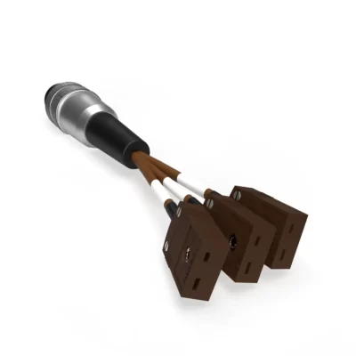
For a full list of probes that are compatible with this Transmitter, please view the ‘Accessories’ tab.
RF542 Probe and UKAS Configurator Instructions
Using the drop down menus above, it is possible to build your RF542 package, by adding the probe you require and then adding UKAS certification at one of our pre-defined temperature ranges.
If you need an option, or temperatures, that is not available as part of this configurator please click here to contact us and we’ll be happy to help.
Battery Change Process
To change the battery in your RF542 Remote Temperature Monitor simply follow the following steps:

- Remove mains power from the RF542 Remote Temperature Monitor
- Undo the battery cover and remove the Lithium AA battery
- Wait for the screen to go off completely
- Insert the new RF542BATT and re-fit the battery cover
- Re-connect the mains power
- The RF542 Remote Temperature Monitor should re-connect to the Gateway automatically
- Dispose of the old battery safely – Note Lithium Batteries should not be disposed of in General Waste
Technical Specifications
| Name | Value |
|---|---|
| Packaging Contents | 1x RF542 (including 3.6V AA Lithium Battery), 1x RF542 Wall Mount Bracket, 2x Cable Ties, 1x RF520 AC Adapter Including Regional Adapter, 1x Cat5e Ethernet Cable, 1x RF525 Transmitter Activator, 1x RF542 Quick Reference Guide |
| Operating Temperature Range | 0°C to 50°C 10-90%RH Non-condensing |
| Temperature Measurement Range - External Sensor | -40°C to +125°C / - 40°F to +257°F |
| System Accuracy with External Thermistor -20°C to +70°C | ±0.5°C / ±0.9°F |
| System Accuracy with External Thermistor - Full Range | ±1°C / ±2°F |
| Resolution Temperature - Thermistor | 0.1°C / 0.2°F |
| Door Sensor | 7.5 seconds |
| Storage Temperature | -40°C to +85°C / -40°F to +185°F |
| Ethernet Connectivity | Fixed 100Mbps Half Duplex RJ45 |
| Network Configuration | DHCP |
| Clock Accuracy | 20ppm (1 minute/month) at 25°C / 77°F |
| Logging Memory | 32,000 records |
| Logging Frequency | Programmable between 1 minute and 60 minutes |
| Monitoring Frequency | 1 minute |
| LEDs | Red (Front Label) - Alarm Green (Front Label) - External Power Green (Side) - LAN Connection |
| Case Material | Over Moulded food safe clear Polycarbonate with BioCote® antimicrobial |
| Battery Type | Replaceable Lithium AA Cell 3.6V |
| Battery Life | Up to 2 years backup, Normal operation requires RF520 (Supplied) |
| Dimensions | L 83mm x W 107mm D 40mm |
| Weight | 215g |
| Probe Attachment Required | A standard Comark probe is required for operation of this device |
| Warranty | 2 Years |
*You will need to Sign In to view additional content
Documentation
Downloads
| Name | Version | Size | Date | |
|---|---|---|---|---|
| RF542 Remote Temperature Monitor Firmware | 3.0.3 | 27.59 KB | 4th December 2014 |
Articles / FAQs
| Name | Date | ||||||||||
|---|---|---|---|---|---|---|---|---|---|---|---|
What battery do I need for my RF542?
What battery do I need for my RF542?The Lithium Battery required for the correct operation of the RF542 Remote Temperature Monitor is a Xeno AA Lithium Cell, model XL-060F. This cell can be obtained from most battery specialists or direct from Comark, order RF542BATT. The use of any other type of 3.6V Lithium cell may not provide you with the normal battery life and correct operation of the RF542 Remote Temperature Monitor might be affected.
|
17th June 2015 | ||||||||||
Transmitters show ‘No signal’
Transmitters show ‘No signal’On occasion you may appear to suffer ‘signal loss’ between your Gateway device and your Transmitters. Initially, you should confirm that there are no ‘Low Battery’ warnings showing for your Transmitters on your Gateway Device. Transmitters show ‘No signal’ when they have been continuously out of contact with the Gateway for a duration of 5 times the radio rate or a minimum of 1 hour. For the standard radio rate of 15 minutes, this amounts to approximately 1 hour 15 minutes before a ‘No signal’ is flagged. In that time, the Gateway has determined that it has not received a valid signal/data packet from the Transmitter. The table below details some basic troubleshooting, should you encounter this issue:
|
18th November 2014 | ||||||||||
Batteries only last a few months
Batteries only last a few monthsBattery life quoted for RF5xx Transmitters makes a number of assumptions about the operating use and conditions. Transmitters are assumed only to transmit one data record to your RF500A/AP Gateway every 15 minutes. Operation of the Transmitter is assumed to be at ambient, approx. 23°C. Deviations from this specification will have an effect on the battery life of each Transmitter. For example:
|
|||||||||||
Low battery indication does not clear
Low battery indication does not clearThe ‘Low Battery’ message on the homepage of the Gateway might not clear immediately after you have changed the battery of one of your transmitters.
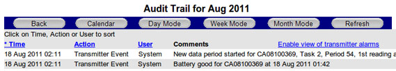
When a Transmitter battery is replaced, it generates a ‘Battery Good’ event record and queues it for transmission to the Gateway. The ‘Low Battery’ message on the Homepage of the Gateway is cleared when the Gateway receives this ‘Battery Good’ record from the Transmitter. This event record is also posted to the Audit Trail as pictured below.
The Transmitter data queue could be several thousand records long and may take several hours before the ‘Battery Good’ record is sent. You can check this progress by looking for the last data on the homepage of the Transmitter. When the data is up-to-date then the ‘Low Battery’ warning should also clear. The best way to avoid this delay is to change the battery soon after the first ‘Low Battery’ warning message is posted on the Gateway homepage. The longer the Transmitter is left in the low battery condition the longer the data record queue becomes. Beware of re-tasking the Transmitter, because the data record queue is cleared as a result. The ‘Battery Good’ record will also be cleared and the Gateway ‘Low Battery’ message will not clear even through the Transmitter appears to be working normally. Should this happen, then simply remove and refit the battery of the Transmitter in question, so that the Transmitter believes that a new battery has been fitted.
|
|||||||||||
Door Sensor Alarms Explained
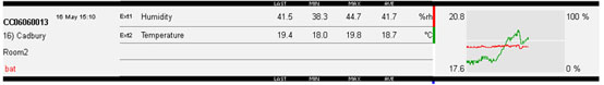
Door Sensor Alarms ExplainedThe following information explain the types of alarms generated by the Door Sensors connected to your RF500 Monitoring System. Continuous Door AlarmsA Continuous Door Alarm is defined as an alarm that is triggered whenever a door is left continuously open for a period of more than X minutes. Please refer to the ‘Door Alarms’ chapter under ‘Transmitter Alarms’ in the RF500-Webview Help Guide for a detailed explanation of Continuous Door Alarms. Average Door AlarmsAn average Door Alarm Door is defined as an alarm that is triggered whenever a door is left open for more than X minutes cumulatively, in a given period of up to 60 minutes. This alarm captures many individual shorter door open times, that may fail to trigger a continuous door alarm, but are nonetheless still important. Please refer to the ‘Door Alarms’ chapter under ‘Transmitter Alarms’ in the RF500-Webview Help Guide for a detailed explanation of Average Door Alarms. Reading Door Alarm DataBoth continuous and average door alarms are enabled or disabled together, therefore if the average door alarm is not required, setting the average limit equal to the average period causes the average alarm never to occur because the limit can not be exceeded. Whenever a continuous door alarm is triggered an Event only is generated, tabular data will not be coloured to indicate the alarm.
A representation of tabular data shown above shows a typical reading. The readings reported for the door channel are given as two values:
The percentage gives a measure of how much time a door actually spends opened which could represent a problem in a real world application. Consider the following scenario: A door to a laboratory is monitored using RF500 and the continuous alarm is set to 20 minutes to capture a “door left open” event. If that door is opened then closed after 19 minutes have elapsed, then immediately opened again for 19 minutes then closed, the continuous alarm event would not have been generated; however that door has effectively been open for 38 minutes during the previous 40 minutes or so. With an averaging interval of 60 minutes the RF500 system would report a door reading of approximately 63% or with an averaging interval of 40 minutes a door reading of close to 100% would be reported. It may be the case that this high level of “door open” condition may cause environmental controls to be overloaded.
|
19th November 2014 | ||||||||||
RF5xx Transmitter Status Codes (COdE) Explained
RF5xx Transmitter Status Codes (COdE) ExplainedUnder certain conditions your RF5xx Transmitter might display a Status Code on the LCD screen which takes the form of the word ‘COdE’ followed by either a 3- or 4-digit alphanumeric sequence. These Status Codes can help in diagnosing the reason why a Transmitter might be failing to transmit data to the Gateway.
The ‘COdE’ based message is only seen on RF5xx Transmitters with Firmware Version 3.0.0 or higher. It is worth noting that Status Codes generally indicate a problem, that can be resolved by the user. For detailed information on the Status Code that your RF5xx Transmitter is displaying, please select the appropriate code from those listed below:
|
6th November 2014 | ||||||||||
RF5xx Transmitter Fault Messages (FAULt) Explained
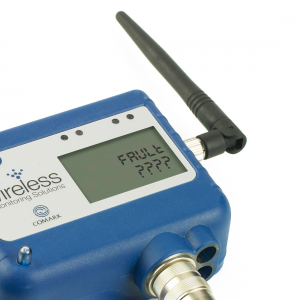
RF5xx Transmitter Fault Messages (FAULt) ExplainedUnder certain conditions your RF51x Transmitter might display a Fault Message on the LCD screen which takes the form of the word ‘FAULt’ followed by either a 3- or 4-digit alphanumeric sequence. These Fault Messages are alerting you to a failure of some kind within the device.
A ‘FAULt’ based message is only seen on RF5xx Transmitters with Firmware Version 3.0.0 or higher. It is worth noting that Fault Messages generally cannot be resolved by the user. For detailed information on the particular Fault Message that your RF5xx Transmitter is displaying, please select the appropriate variant from those listed below:
This article refers to a Fault message seen on Transmitters with Firmware Version 3.0.0 or higher. The following full fault messages are covered by this article: 001,101,201,301,401,501,601,701,801,901,A01,B01,C01,D01,E01,F01,1001,1101,1201,1301,1401,1501,1601,1701,1801,1901,1A01, 1B01,1C01,1D01,1E01,1F01,002,102,202,302,402,502,602,702,802,902,A02,B02,C02,D02,E02,F02,1002,1102,1202,1302,1402,1502,1602,1702,1802,1902,1A02, 1B02,1C02,1D02,1E02,1F02,004,104,204,304,404,504,604,704,804,904,A04,B04,C04,D04,E04,F04,1004,1104,1204,1304,1404,1504,1604,1704,1804,1904,1A04, 1B04,1C04,1D04,1E04,1F04,008,108,208,308,408,508,608,708,808,908,A08,B08,C08,D08,E08,F08,1008,1108,1208,1308,1408,1508,1608,1708,1808,1908,1A08, 1B08,1C08,1D08,1E08,1F08
|
|||||||||||
RF5xx Transmitter Error Messages (ErrOr) Explained
RF5xx Transmitter Error Messages (ErrOr) ExplainedUnder certain conditions your RF5xx Transmitter might display an Error Message on the LCD screen which takes the form of the word ‘ErrOr’ followed by either a 3- or 4-digit alphanumeric sequence. These Error Messages can help in diagnosing the reason why a Transmitter might be failing to transmit data to the Gateway.
The ‘ErrOr’ based message is only seen on RF5xx Transmitters with a Firmware Version 2.4.2 or lower. It is worth noting that these Error Messages generally indicate a problem, that can be resolved by the user. For detailed information on the Error Message that your RF5xx Transmitter is displaying, please select the appropriate code from those listed below:
|
27th January 2015 |


-
LITECLOUDNEW

Diligence Cloud – Lite Plan
-
PLUSCLOUDNEW

Diligence Cloud – Plus Plan
-
PREMCLOUDNEW

Diligence Cloud – Premium Plan
-
N2000ADP/T
N2000 Adapter Type T
-
N2000ADP/K

N2000 Adapter Type K
-
N2013
Temperature and Humidity Data Logger